CMT calculations are carried out over a computational window
![]() =
= ![]()
![]() m,
m,
![]() =
=
![]() m with stepsizes
m with stepsizes
![]() m,
m,
![]() m. For the
spectrum evaluation, quadratic interpolation is used with nodal wavelengths
m. For the
spectrum evaluation, quadratic interpolation is used with nodal wavelengths
![]() m,
m,
![]() m,
m,
![]() m. At these nodal wavelengths,
as shown in Table 4.1, the straight waveguides are bimodal
and the bent waveguide (ring segment) is ``monomodal'' (i.e. the bend does not
support other modal fields with reasonably low attenuation).
m. At these nodal wavelengths,
as shown in Table 4.1, the straight waveguides are bimodal
and the bent waveguide (ring segment) is ``monomodal'' (i.e. the bend does not
support other modal fields with reasonably low attenuation).
| |||||||||||||||||||||||||
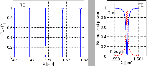
The resultant spectral response of the ringresonator is shown in
Figure 4.11. Even though the straight waveguides are
bimodal, due to the ``phase matching'' condition (see the values in
Table 4.1), practically no power is coupled to the TE![]() straight waveguide mode. In good qualitative agreement with Ref. [56],
the plots represent the output powers for the
fundamental TE mode of the straight waveguide. The left plot of Figure 4.11 shows sharp resonances of the transmitted
power, whereas the plot on the right side magnifies the resonance features at
straight waveguide mode. In good qualitative agreement with Ref. [56],
the plots represent the output powers for the
fundamental TE mode of the straight waveguide. The left plot of Figure 4.11 shows sharp resonances of the transmitted
power, whereas the plot on the right side magnifies the resonance features at
![]() . At this resonance wavelength, the CMT
simulations predict a full width at half maximum (FWHM)
. At this resonance wavelength, the CMT
simulations predict a full width at half maximum (FWHM)
![]() nm, a quality factor
nm, a quality factor
![]() , while Ref. [56]
quotes
, while Ref. [56]
quotes
![]() nm,
nm,
![]() .
.
 |
A comparison of the resonance wavelengths obtained by the CMT simulations and
the results of Ref. [56] is shown in
Table 4.2. On the micron scale these results agree up
to the second decimal place. For applications, where the positions of the
resonance wavelengths on a large wavelength range (as e.g. in the left plot
of Figure 4.11) is relevant, one can consider the
difference relative to the free spectral range (FSR), i.e. look at the
expression
![]() . For the TE
. For the TE![]() resonance at
resonance at
![]() , one obtains a
small deviation of about
, one obtains a
small deviation of about ![]() ; in this respect, we find a reasonable
agreement between FDTD and CMT simulations. On the other hand, for
applications that involve a fine sampling of wavelengths, one might be
interested in the deviation relative to the resonance width (FWHM), given by
; in this respect, we find a reasonable
agreement between FDTD and CMT simulations. On the other hand, for
applications that involve a fine sampling of wavelengths, one might be
interested in the deviation relative to the resonance width (FWHM), given by
![]() . This leads to a
deviation of about
. This leads to a
deviation of about ![]() , i.e. the computational values for the resonance
positions become meaningless in this respect.
, i.e. the computational values for the resonance
positions become meaningless in this respect.
Note that for the present
configuration, it is difficult to access the reliability of the CMT or the FDTD
approach. The corresponding ring resonator with the high refractive index
contrast represents an extreme configuration for the CMT approach. Also, the
FDTD computations are seriously constrained by inherent numerical
dispersion. Therefore we do not attempt a statement about which of the
simulations corresponds to physical reality, what concerns the precise
resonance positions.
| ||||||||||||||||||
By filling the interior of the ring waveguide in Section 4.4.3
with the core material, one obtains a microdisk resonator. For this structure,
we now compare CMT results with Ref. [56]. As before, the TE![]() mode
is excited at the In-port, the spectral response is computed with quadratic
interpolation at nodal wavelengths
mode
is excited at the In-port, the spectral response is computed with quadratic
interpolation at nodal wavelengths
![]() m
m![]() m
m![]() m. For the present setting, apart from the straight waveguide modes, the
first three lower order cavity modes are sufficient as basis
fields. Table 4.3 gives their effective refractive
indices at the nodal wavelengths.
m. For the present setting, apart from the straight waveguide modes, the
first three lower order cavity modes are sufficient as basis
fields. Table 4.3 gives their effective refractive
indices at the nodal wavelengths.
|
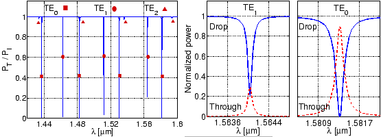
As in the case of the corresponding microring configuration, again here most of
the input power is coupled to only the TE![]() mode of the straight
waveguides. The spectral response of this microdisk resonator is shown in
Figure 4.12; we again find a reasonable qualitative
agreement with Ref. [56]. As evident from the plot on the left side,
for the present configuration, only the TE
mode of the straight
waveguides. The spectral response of this microdisk resonator is shown in
Figure 4.12; we again find a reasonable qualitative
agreement with Ref. [56]. As evident from the plot on the left side,
for the present configuration, only the TE![]() and TE
and TE![]() cavity modes play a significant role. Details of the resonances are shown in
the associated plots.
cavity modes play a significant role. Details of the resonances are shown in
the associated plots.
 |
Note that these plots are obtained by quadratic interpolation of CMT results
for scattering matrices ![]() and cavity segment propagation constants
and cavity segment propagation constants
![]() at just three nodal wavelengths, whereas to resolve such
sharp features with FDTD simulations, one has to do FDTD calculations over
extremely large time intervals, which turns out to be demanding in terms of
computational effort.
at just three nodal wavelengths, whereas to resolve such
sharp features with FDTD simulations, one has to do FDTD calculations over
extremely large time intervals, which turns out to be demanding in terms of
computational effort.
The corresponding comparison of resonant wavelengths computed with CMT simulations and values of Ref. [56] is given in Table 4.4. As in the case of the previously discussed ringresonator, the remarks concerning the accuracy of the two simulation techniques with respect to the resonance positions apply to these results as well.