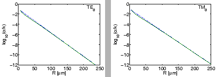
|
For purposes of validating our implementation we start with a comparison of phase propagation constants and attenuation levels. Tables 2.1 and 2.2 list values for angular mode numbers obtained with the present mode solver for two bend configurations adopted from Ref. [43], together with reference data from that source. We found an excellent overall agreement, for both the configurations with higher (Table 2.1) and lower refractive index contrast (Table 2.2).
|
|
The discussion of bent waveguides in Ref. [43] applies an alternative
definition of the bend radius ![]() as the distance from the origin to the
center of the core layer, which is related to the radius
as the distance from the origin to the
center of the core layer, which is related to the radius ![]() as introduced in
Figure 2.1 by
as introduced in
Figure 2.1 by
![]() (hence the unusual values of bend radii in
Tables 2.1, 2.2). Both definitions are meant as descriptions
of the same physical configuration, i.e. both lead to the same angular field
dependence (2.1), given in terms of the azimuthal mode
numbers
(hence the unusual values of bend radii in
Tables 2.1, 2.2). Both definitions are meant as descriptions
of the same physical configuration, i.e. both lead to the same angular field
dependence (2.1), given in terms of the azimuthal mode
numbers ![]() as determined by the dispersion equation (2.7). Via
the relation
as determined by the dispersion equation (2.7). Via
the relation
![]() , the different choices of the bend
radius result in different values
, the different choices of the bend
radius result in different values ![]() and
and
![]() for the propagation constant, and consequently in different values
for the propagation constant, and consequently in different values ![]() ,
,
![]() and
and ![]() ,
, ![]() for the phase and attenuation constants.
for the phase and attenuation constants.
Still, for many applications one is interested in the variation of the phase
constant and the attenuation with the curvature of the bend, expressed by the
bend radius. Figure 2.2 shows corresponding plots for the
configuration of Table 2.1, including values for the two different
bend radius definitions. While on the scale of the figure the differences are
not visible for the attenuation constants, the levels of the phase propagation
constants differ indeed substantially for smaller bend radii. As expected, for
low curvature the values of both ![]() and
and ![]() tend to the
effective indices of straight slab waveguides with equivalent refractive index
profile. For the present low contrast configuration, only minor differences
between TE and TM polarization occur.
tend to the
effective indices of straight slab waveguides with equivalent refractive index
profile. For the present low contrast configuration, only minor differences
between TE and TM polarization occur.
 |
Certainly no physical reasoning should rely on the entirely arbitrary
definition of the bend radius. This concerns e.g. statements about the growth
or decay of phase propagation constants with ![]() (according to
Figure 2.2 the sign of the slope can indeed differ), or
discussions about the ``phase matching'' of bent waveguides and straight
channels in coupler or microresonator configurations. Care must be taken that
values for
(according to
Figure 2.2 the sign of the slope can indeed differ), or
discussions about the ``phase matching'' of bent waveguides and straight
channels in coupler or microresonator configurations. Care must be taken that
values for ![]() and
and ![]() or effective quantities like
or effective quantities like ![]() are
used with the proper definition of
are
used with the proper definition of ![]() taken into account.
taken into account.
With the present (semi) analytic solutions at hand, we have now a possibility
to validate ``classical'' expressions for the variation of the bend
attenuation with the bend radius. Beyond the high curvature region,
Figure 2.2 shows a strict exponential decay of ![]() with
respect to
with
respect to ![]() , as predicted by an approximate loss formula for symmetric bent
slabs given in [93, Eq. 9.6-24]:
, as predicted by an approximate loss formula for symmetric bent
slabs given in [93, Eq. 9.6-24]:
 |