Consider a bent slab waveguide with the ![]() -axis as the axis of symmetry as
shown in Figure 2.1. We assume that the material properties and the
fields do not vary in the
-axis as the axis of symmetry as
shown in Figure 2.1. We assume that the material properties and the
fields do not vary in the ![]() -direction. Being specified by the radially
dependent refractive index
-direction. Being specified by the radially
dependent refractive index ![]() (here
(here ![]() is piecewise constant), the
waveguide can be seen as a structure that is homogeneous along the angular
coordinate
is piecewise constant), the
waveguide can be seen as a structure that is homogeneous along the angular
coordinate ![]() . Hence one chooses an ansatz for the bend modes with pure
exponential dependence on the azimuthal angle, where the angular mode number
is commonly written as a product
. Hence one chooses an ansatz for the bend modes with pure
exponential dependence on the azimuthal angle, where the angular mode number
is commonly written as a product ![]() with a reasonably defined bend
radius
with a reasonably defined bend
radius ![]() , such that
, such that ![]() can be interpreted as a propagation constant.
can be interpreted as a propagation constant.
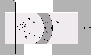 |
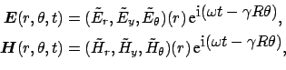
In the cylindrical coordinate system
![]() , the functional form (in
the usual complex notation) of the propagating electric field
, the functional form (in
the usual complex notation) of the propagating electric field
![]() and the
magnetic field
and the
magnetic field
![]() reads
reads
Note that the angular behaviour of the field (2.1) is
determined by the product ![]() , where the definition of
, where the definition of ![]() is entirely
arbitrary. Given a bend mode, the values assigned to the propagation constant
is entirely
arbitrary. Given a bend mode, the values assigned to the propagation constant
![]() change, if the same physical solution is described by using different
definitions of the bend radius
change, if the same physical solution is described by using different
definitions of the bend radius ![]() . We will add a few more comments on this
issue in Section 2.4. The definition of the bend radius
. We will add a few more comments on this
issue in Section 2.4. The definition of the bend radius ![]() as the
radial position of the outer interface of the core layer is still applicable
in case the guiding is effected by a single dielectric interface only, i.e. for the description of whispering gallery modes (see Section
2.4.5). Hence, for this paper we stick to the definition of
as the
radial position of the outer interface of the core layer is still applicable
in case the guiding is effected by a single dielectric interface only, i.e. for the description of whispering gallery modes (see Section
2.4.5). Hence, for this paper we stick to the definition of ![]() as
introduced in Figure 2.1.
as
introduced in Figure 2.1.
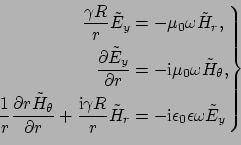
If the ansatz (2.1) is inserted into the Maxwell equations, one obtains the two separate sets of equations
For transverse electric (TE) waves the only nonzero components are
![]() ,
,
![]() and
and
![]() , which are expressed
in terms of
, which are expressed
in terms of
![]() , while for transverse magnetic (TM) waves the only
nonzero components are
, while for transverse magnetic (TM) waves the only
nonzero components are
![]() ,
,
![]() and
and
![]() , which are given by
, which are given by
![]() . Within radial
intervals with constant refractive index
. Within radial
intervals with constant refractive index ![]() , the basic electric and magnetic
components are governed by a Bessel equation with complex order
, the basic electric and magnetic
components are governed by a Bessel equation with complex order ![]() ,
,
Eq. (2.4), together with the interface conditions and suitable
boundary conditions for
![]() and
and
![]() , represents
an eigenvalue problem with the bend mode profiles
, represents
an eigenvalue problem with the bend mode profiles ![]() as eigenfunctions,
and the propagation constants
as eigenfunctions,
and the propagation constants ![]() or angular mode numbers
or angular mode numbers
![]() as eigenvalues. The equation is solved piecewise in the regions with
constant refractive index. While the procedure is in principle applicable for
arbitrary multilayer bent waveguides, for the sake of brevity we discuss here
the three layer configuration as introduced in Figure 2.1.
as eigenvalues. The equation is solved piecewise in the regions with
constant refractive index. While the procedure is in principle applicable for
arbitrary multilayer bent waveguides, for the sake of brevity we discuss here
the three layer configuration as introduced in Figure 2.1.
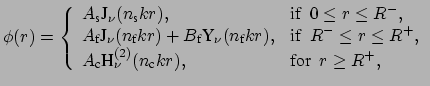
The general solution of Eq. (2.4) is a linear combination of the
Bessel functions of the first kind J and of the second kind
Y. This representation is applicable to the core region. Since
Y tends to ![]() if
if
![]() , for the boundedness of the
electric/magnetic field at the origin one selects only the Bessel function of
the first kind J for the interior region. In the outer region, we
are looking for a complex superposition of J and Y that
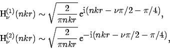
represents outgoing waves. Such a solution can be given in terms of the
Hankel functions of the first kind
H
, for the boundedness of the
electric/magnetic field at the origin one selects only the Bessel function of
the first kind J for the interior region. In the outer region, we
are looking for a complex superposition of J and Y that
represents outgoing waves. Such a solution can be given in terms of the
Hankel functions of the first kind
H![]() or of the second kind
H
or of the second kind
H![]() . Using the asymptotic expansions of these functions
[73, chap. 9, Eq. (9.2.3), Eq. (9.2.4)]
. Using the asymptotic expansions of these functions
[73, chap. 9, Eq. (9.2.3), Eq. (9.2.4)]
The polarization dependent interface conditions lead to a homogeneous system
of linear equations for
![]() ,
,
![]() ,
,
![]() and
and
![]() . The condition for a nontrivial solution can be given the form
. The condition for a nontrivial solution can be given the form
For the numerical implementation, Eq. (2.7) is rearranged as
| J |
|||
Y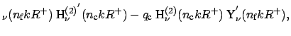 |
|||
| Y |
|||
J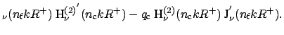 |
In contrast to common notions about leaky modes, the fields obtained by the
ansatz (2.6) do not diverge for large radial coordinate ![]() .
The asymptotic expansion (2.5) predicts a decay
.
The asymptotic expansion (2.5) predicts a decay
![]() . No difficulties related to `large' terms are to be expected for
the numerical evaluation of Eq. (2.8). Moreover, as shown
below, with the squared mode profile being accompanied by a factor
. No difficulties related to `large' terms are to be expected for
the numerical evaluation of Eq. (2.8). Moreover, as shown
below, with the squared mode profile being accompanied by a factor ![]() in
the relevant expression, the bend modes can even be normalized with respect to
the azimuthal mode power.
in
the relevant expression, the bend modes can even be normalized with respect to
the azimuthal mode power.
 TE
TE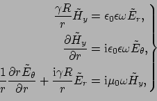 TM
TM