The model of Section 2.2 covers those configurations with the formal
choice
![]() in Figure 2.1, where
in Figure 2.1, where ![]() becomes
irrelevant. The above mentioned transition of a bend mode towards a WGM is
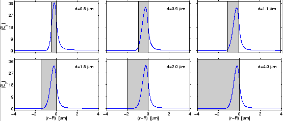
shown in Figure 2.10. For illustration purposes, we adopt a
set of parameters from Ref. [57], that specifies a high-contrast
curved interface with a rather small radius, i.e. a parameter regime that
differs considerably from the previous bent slabs. For the present
configuration, the field profiles of the TE
becomes
irrelevant. The above mentioned transition of a bend mode towards a WGM is
shown in Figure 2.10. For illustration purposes, we adopt a
set of parameters from Ref. [57], that specifies a high-contrast
curved interface with a rather small radius, i.e. a parameter regime that
differs considerably from the previous bent slabs. For the present
configuration, the field profiles of the TE![]() mode for
mode for
![]() m
m![]() m, and
m, and
![]() m are almost identical.
m are almost identical.
 |
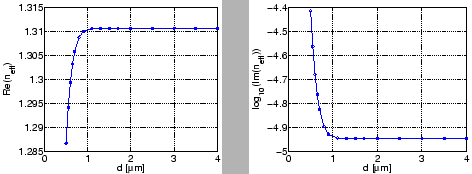
In fact, plots of the propagation constants for these modes in
Figure 2.11 show that for core widths larger than
![]() m,
m,
![]() becomes almost independent from the core width. For
increasing core width, a larger part of the mode profile is trapped inside the
core. This results in the increase of the phase constant
becomes almost independent from the core width. For
increasing core width, a larger part of the mode profile is trapped inside the
core. This results in the increase of the phase constant ![]() and the
decrease of the attenuation constant
and the
decrease of the attenuation constant ![]() .
.
 |
A comparison of the present analytical simulation results for the propagation
constants of the four lowest order WGMs with FDTD results from
Ref. [57] is shown in Table 2.4. Again we find a very good
agreement.
|
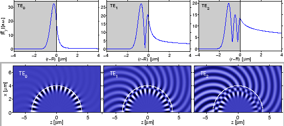
As shown in Figure 2.12, for growing mode order, qualitatively one finds the increase of the attenuation, the outwards shift of the outermost profile intensity maxima, the raise of the exterior field levels, and the wider radial extent of the profiles, just as for the modes of the bent cores in Figs. 2.7 and 2.9. In contrast to the impression given e.g. in Refs. [96,98], the complex mode profiles exhibit minima in the absolute value of the principal field component, not nodal points.
 |
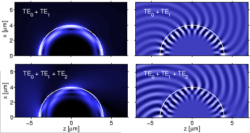
Despite the substantial differences in the attenuation levels of these modes, the higher order fields may well play a role for the representation of resonances of the corresponding disc-shaped microresonator cavity, due to the rather short circumference. Therefore we conclude this section with two examples of interferences of whispering gallery modes in Figure 2.13. As for the bend slabs in Figure 2.8 one observes an interior beating pattern and ray-like bundles of waves in the exterior, here on much shorter ranges in terms of the local wavelength.
 |