 |
 |
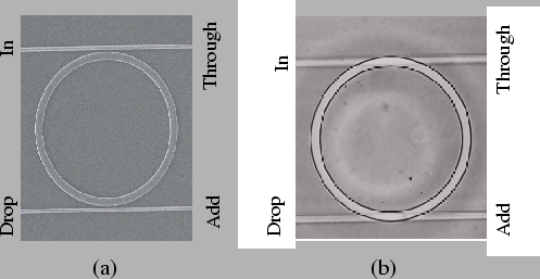
Conventionally, the functioning of microresonators is described by the interaction of harmonic optical waves propagating along the straight waveguide and the cavity, and the interferometric resonances of the waves inside the cavity [33]. A single frequency optical wave is launched at the In-port of the resonator. As this signal propagates along the upper straight waveguide, that connects the In-port and Through-port, part of it is evanescently coupled to the cavity. While propagating along the cavity, part of this signal is coupled to the lower straight waveguide and appears at the Drop-port. The remaining part of the signal propagates along the cavity, and interferes with the newly in-coupled signal in the upper interaction region. Depending upon the specific configuration, these two fields undergo constructive or destructive interference.
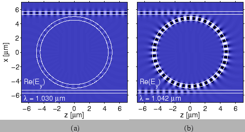
If the cavity field is out of phase with the newly entering field, then destructive interference takes place inside the cavity and as a result, there is only a small amount of power inside the cavity. Under so-called off resonance conditions, as shown in Fig. 1.2(a), most of the input power is directly transmitted to the Through-port, and there is comparably low power at the Drop-port.
On the other hand, if the field inside the cavity is in phase with the newly in-coupled signal, then due to constructive interference, energy builds up inside the cavity. This field gets coupled to the Drop-port waveguide. Under so-called resonance conditions, there is a significant power observed at the Drop-port, while less power appears at the Through-port. This situation is shown in Fig. 1.2(b).
 |
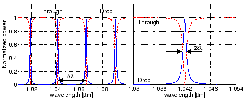
A typical spectral response of a microresonator device is shown in Fig. 1.3. Resonances appear as dips in the Through-port power curve and peaks in the Drop-port power curve. In other words, the wavelengths for which a microresonator is on resonance, will be ``dropped'' at the Drop-port. Also, for a symmetrical device, if a new signal that corresponds to a resonance wavelength is launched at the Add-port, it will get ``added'' to the off resonance signal launched at the In-port, and appears at the Through-port. Therefore the arrangement shown in Fig. 1.1 can be used as an add/drop filter.
 |