We have applied a standard Finite Difference Time Domain (FDTD) scheme
[94,95], where a computational window of
![]() m
m![]() is
discretized uniformly by a mesh with step sizes of
is
discretized uniformly by a mesh with step sizes of
![]() m. Perfectly
matched layer (PML) boundary conditions enclose the computational domain, with
a width of
m. Perfectly
matched layer (PML) boundary conditions enclose the computational domain, with
a width of ![]() points, a quadratic envelope, and a strength such that the
theoretical reflectivity of a wave propagating through the background material
at normal incidence is
points, a quadratic envelope, and a strength such that the
theoretical reflectivity of a wave propagating through the background material
at normal incidence is ![]() . The interior of the computational window
contains the ring with parameters as given for Figure 2.6 and the
straight waveguide with the same refractive index profile, with a gap of
. The interior of the computational window
contains the ring with parameters as given for Figure 2.6 and the
straight waveguide with the same refractive index profile, with a gap of
![]() m in between. A modal field is launched into the straight core using
the total field /scattered field approach [55]. Its amplitude is
raised according to a half-Gaussian curve with a waist of
m in between. A modal field is launched into the straight core using
the total field /scattered field approach [55]. Its amplitude is
raised according to a half-Gaussian curve with a waist of
![]() fs, with
the maximum being reached at
fs, with
the maximum being reached at
![]() fs. After this time, the incident
field amplitude is kept constant. The simulation runs for a time of
fs. After this time, the incident
field amplitude is kept constant. The simulation runs for a time of
![]() ps with a time step of
ps with a time step of
![]() fs, after which the ramp of
the wave has gone around the ring approximately once.
fs, after which the ramp of
the wave has gone around the ring approximately once.
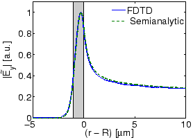 |
Figure 2.6 shows an excellent agreement of the approximation for
the bend mode profile obtained in this way with the result of the analytical
bend mode solver. We also found a very good agreement of the attenuation
constant
![]() m
m![]() estimated by the FDTD simulation with the
analytic result
estimated by the FDTD simulation with the
analytic result
![]() m
m![]() . Hence comparisons of this kind
can confirm the expectation that the bend modes as introduced in
Eq. (2.1) are indeed suitable basis fields for a (2-D)
description of cylindrical microresonator configurations.
. Hence comparisons of this kind
can confirm the expectation that the bend modes as introduced in
Eq. (2.1) are indeed suitable basis fields for a (2-D)
description of cylindrical microresonator configurations.