2D microresonators simulator

|
2D microresonators simulator |
|
Circular integrated optical microresonators are increasingly employed as compact and versatile wavelength filters. Here we present a 2-D frequency domain simulation tool for these devices.
The resonators are functionally represented in terms of two couplers with appropriate connections using bent and straight waveguides. The abstract scattering matrices of these couplers and the propagation constants of the cavity bends allow to compute the spectral responses of the resonators. These parameters are calculated by means of the rigorous analytical model of bent waveguides, and the spatial coupled mode theory model of the constituent bent-straight waveguide couplers.
The resonators investigated here consist of ring or disk shaped dielectric
cavities, evanescently coupled to two parallel straight bus cores. The
waveguides are made of linear and nonmagnetic materials. We consider
guided-wave scattering problems in the frequency domain, where a time-harmonic
optical signal
![]() i
i![]() of given real frequency
of given real frequency
![]() is present everywhere. Cartesian coordinates
is present everywhere. Cartesian coordinates ![]() ,
, ![]() are introduced
for the spatially two dimensional description as shown in
Figure 1. The structure and all TE- or TM-polarized optical
fields are assumed to be constant in the
are introduced
for the spatially two dimensional description as shown in
Figure 1. The structure and all TE- or TM-polarized optical
fields are assumed to be constant in the ![]() -direction.
-direction.

|
Schematic microresonator representation: A cavity of radius |
Adhering to the most common description for microring-resonators [2,3], the devices are divided into two bent-straight waveguide couplers,
which are connected by segments of the cavity ring. Half-infinite pieces of
straight waveguides constitute the external connections, where the letters A,
B,
![]() ,
,
![]() (external) and a, b,
(external) and a, b,
![]() ,
,
![]() (internal) denote the coupler ports. If
one accepts the approximation that the interaction between the optical waves
in the cavity and in the bus waveguides is negligible outside the coupler
regions, then this functional decomposition reduces the microresonator
description to the mode analysis of straight and bent waveguides, and the
modeling of the bent-straight waveguide couplers.
(internal) denote the coupler ports. If
one accepts the approximation that the interaction between the optical waves
in the cavity and in the bus waveguides is negligible outside the coupler
regions, then this functional decomposition reduces the microresonator
description to the mode analysis of straight and bent waveguides, and the
modeling of the bent-straight waveguide couplers.
Assuming that all transitions inside the coupler regions are sufficiently
smooth, such that reflections do not play a significant role for the resonator
functioning, we further restrict the model to unidirectional wave propagation,
as indicated by the arrows in Figure 1. Depending on the
specific configuration, this assumption can be justified or not.
Go to top
Consider coupler (I) first. Suppose that the straight cores support
![]() guided modes with propagation constants
guided modes with propagation constants
![]() ,
,
![]() . For the cavity,
. For the cavity,
![]() bend modes are taken
into account. Due to the radiation losses, their propagation constants
bend modes are taken
into account. Due to the radiation losses, their propagation constants
![]() ,
,
![]() , are complex valued [4]. Here
, are complex valued [4]. Here
![]() ,
,
![]() and
and
![]() are real
positive numbers. The variables
are real
positive numbers. The variables ![]() ,
, ![]() , and
, and ![]() ,
, ![]() , denote
the directional amplitudes of the properly normalized ``forward'' propagating
(clockwise direction, cf. Figure 1) basis modes in the
respective coupler port planes, combined into amplitude (column) vectors
, denote
the directional amplitudes of the properly normalized ``forward'' propagating
(clockwise direction, cf. Figure 1) basis modes in the
respective coupler port planes, combined into amplitude (column) vectors
![]() ,
,
![]() , and
, and
![]() ,
,
![]() . A completely analogous reasoning
applies to the second coupler, where a symbol
. A completely analogous reasoning
applies to the second coupler, where a symbol ![]() identifies the mode
amplitudes
identifies the mode
amplitudes
![]() ,
,
![]() , and
, and
![]() ,
,
![]() at the port planes.
at the port planes.
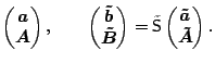
The model of coupler for unidirectional wave propagation
through the coupler regions provides scattering matrices
S,
![]() , such that the coupler operation is represented as
, such that the coupler operation is represented as
| mr.h, mr.c | Circular cavity microresonator (More) |
Microresonators simulator: Example
K. R. Hiremath, R. Stoffer, and M. Hammer.
Modeling of circular integrated optical microresonators by 2-D
frequency domain coupled mode theory.
2005 (accepted).
K. Okamoto.
Fundamentals of Optical Waveguides.
Academic Press, U.S.A, 2000.
M. Hammer, K. R. Hiremath, and R. Stoffer.
Analytical approaches to the description of optical microresonator
devices.
In M. Bertolotti, A. Driessen, and F. Michelotti, editors, Microresonators as building blocks for VLSI photonics, volume 709 of AIP
conference proceedings, pages 48-71. American Institute of Physics,
Melville, New York, 2004.
K. R. Hiremath, M. Hammer, S. Stoffer, L. Prkna, and J. Ctyroký.
Analytic approach to dielectric optical bent slab waveguides.
Optical and Quantum Electronics, 37(1-3):37-61, January 2005.
K. R. Hiremath.
Coupled mode theory based modeling and analysis of circular optical microresonators
Ph. D. thesis, University of Twente, The Netherlands, October 2005.
|
|

|

|

|
|
 S
S