

Next: Concluding remarks
Up: Simulation results
Previous: Coupler with monomodal bent
Contents
Coupler with multimodal bent waveguide
If the core width of a bent waveguide is increased beyond a certain limit,
then as discussed in Section 2.4.5, the whispering gallery regime is
reached, where the modes are guided by just the outer dielectric
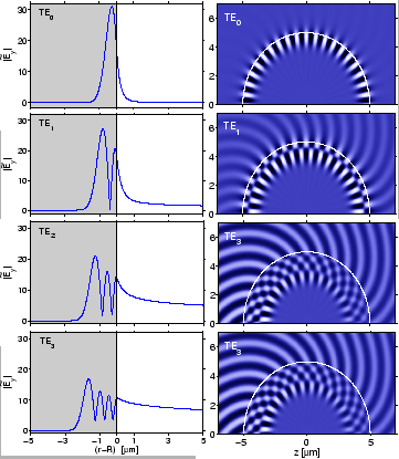
interface. Figure 3.8 illustrates the first four lowest order
whispering gallery modes that are supported by a structure with the parameters
of the previous ring segments, where the interior has been filled
with the core material. If the resulting disk is employed as the cavity in
a resonator structure, all bend modes with reasonably low losses
must be suspected to be relevant for the functioning of the device.
Therefore we now consider bent-straight coupler configurations, where
the bend supports multiple whispering gallery modes.
Figure:
TE polarized whispering gallery modes;
basis fields for the CMT analysis of the multimode couplers of
Section 3.4.2. The plots show the absolute value
 of the radial mode profile (left) and snapshots of the propagating
physical field
  (right). The effective mode indices
 related to the bend radius
 m are
m are
 i
i (TE
(TE ),
),
 i
i (TE
(TE ),
),
 i
i (TE
(TE ), and
 i
i (TE
(TE ), for
 m. All modes are power normalized.
 |
A parameter set similar to Section 3.4.1
is adopted, with
 ,
,
 ,
,
 m,
m,
 ,
,
 ,
,
 m, for
the target wavelength
 m.
The CMT analysis of the coupler structures is carried out on a
computational window
![$ [x_{\mbox{\scriptsize l}}, x_{\mbox{\scriptsize r}}]=[0, 15]\,\mu\mbox{m}$](img834.png) ,
,
![$ [z_{\mbox{\scriptsize i}}, z_{\mbox{\scriptsize o}}]= [-4, 4]\,\mu\mbox{m}$](img835.png) with large extent in
the (radial)
with large extent in
the (radial)  -direction, in order to capture the radiative parts of
the lossy higher order bend fields. Stepsizes for the numerical integrations
are
 m,
m,
 m, as before.
It is not a priori evident, how many basis fields are relevant for a
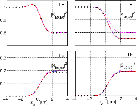
particular simulation. Figure 3.9 shows the effect of the inclusion
of the higher order bend modes on the evolution of the primary coefficients
of the scattering matrix
S.
Figure 3.9:
CMT analysis of the multimode coupler of
Section 3.4.2, effect of the inclusion of higher order
cavity modes on the evolution of the scattering matrix.
Results for TE waves with one (dashed line), two
(dash-dotted line), three (solid line), and four cavity modes (dotted line)
taken into account.
Note the different vertical axes of the plots.
 |
The self coupling coefficient
 of the fundamental bend field is
hardly influenced at all, and there is only a minor effect on the cross
coupling coefficients
 and
and
 . Inclusion of the first order bend field
reduces merely the self coupling coefficient
 of the straight mode
by a substantial amount, due to the additional coupling to that basis field.
Apparently, for the present structure it is sufficient to take just the
two or three lowest order bend modes into account.
This hints at one of the advantages of CMT approach, where one can precisely
analyze the significance of the individual basis modes. We will resume
this issue in Section 4.4.2.
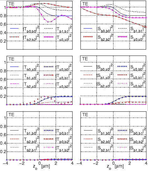
With three cavity fields and the mode of the straight waveguide,
the CMT simulations lead to coupler scattering matrices of dimension
 . Curves for the evolution of the
  elements of the propagation
and scattering matrices
T,
S are collected in
Figure 3.10. Just as in Section 3.4.1, the application
of the projection procedure to extract the stationary levels of
 ,
,
 from the nonstationary quantities
 ,
,
 at the exit port of the coupler is
essential.
Figure:
Evolution of the propagation matrix
T and scattering matrix
S for the coupler configuration with multimode bend as
specified in Section 3.4.2; CMT results with four basis fields.
 |
Again, the agreement of the exit levels of all
cross coupling coefficients indicates that reciprocity is satisfied.
In contrast to Figure 3.3, the noticeable decay of the
self coupling coefficients
 ,
,
 is due to the strong attenuation of
the basis fields, as directly introduced into
S via
equation (3.20).
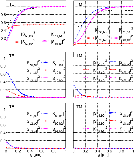
According to Figure 3.11, the elements of the scattering matrix exhibit
a similar variation with the gap width as found for the former monomode
bent-straight waveguide coupler (cf. Figure 3.4).
Figure 3.11:
Scattering matrix elements
 versus the gap width
  for the coupler structures of
Section 3.4.2 for TE (top) and TM polarization (bottom).
The CMT simulations take three whispering gallery modes and the
field of the straight waveguide into account.
 |
With growing
separation distance the cross coupling coefficients tend to zero. The constant
levels attained by the self coupling coefficients of the bent modes are
determined by the power the respective mode loses in traversing the
computational window. Also here, with the exception of configurations
with almost closed gap, we find that cross coupling coefficients
with reversed indices coincide, i.e. that the simulations obey reciprocity.


Next: Concluding remarks
Up: Simulation results
Previous: Coupler with monomodal bent
Contents
Kirankumar Hiremath
2005-09-23


![]() ,
,
![]() ,
,
![]() m,
m,
![]() ,
,
![]() ,
,
![]() m, for
the target wavelength
m, for
the target wavelength
![]() m.
The CMT analysis of the coupler structures is carried out on a
computational window
m.
The CMT analysis of the coupler structures is carried out on a
computational window
![]() ,
,
![]() with large extent in
the (radial)
with large extent in
the (radial) ![]() -direction, in order to capture the radiative parts of
the lossy higher order bend fields. Stepsizes for the numerical integrations
are
-direction, in order to capture the radiative parts of
the lossy higher order bend fields. Stepsizes for the numerical integrations
are
![]() m,
m,
![]() m, as before.
m, as before.

![]() of the fundamental bend field is
hardly influenced at all, and there is only a minor effect on the cross
coupling coefficients
of the fundamental bend field is
hardly influenced at all, and there is only a minor effect on the cross
coupling coefficients
![]() and
and
![]() . Inclusion of the first order bend field
reduces merely the self coupling coefficient
. Inclusion of the first order bend field
reduces merely the self coupling coefficient
![]() of the straight mode
by a substantial amount, due to the additional coupling to that basis field.
Apparently, for the present structure it is sufficient to take just the
two or three lowest order bend modes into account.
This hints at one of the advantages of CMT approach, where one can precisely
analyze the significance of the individual basis modes. We will resume
this issue in Section 4.4.2.
of the straight mode
by a substantial amount, due to the additional coupling to that basis field.
Apparently, for the present structure it is sufficient to take just the
two or three lowest order bend modes into account.
This hints at one of the advantages of CMT approach, where one can precisely
analyze the significance of the individual basis modes. We will resume
this issue in Section 4.4.2.
![]() . Curves for the evolution of the
. Curves for the evolution of the ![]() elements of the propagation
and scattering matrices
T,
S are collected in
Figure 3.10. Just as in Section 3.4.1, the application
of the projection procedure to extract the stationary levels of
elements of the propagation
and scattering matrices
T,
S are collected in
Figure 3.10. Just as in Section 3.4.1, the application
of the projection procedure to extract the stationary levels of
![]() ,
,
![]() from the nonstationary quantities
from the nonstationary quantities
![]() ,
,
![]() at the exit port of the coupler is
essential.
at the exit port of the coupler is
essential.

![]() ,
,
![]() is due to the strong attenuation of
the basis fields, as directly introduced into
S via
equation (3.20).
is due to the strong attenuation of
the basis fields, as directly introduced into
S via
equation (3.20).
