Referring to the classification of resonator types given in [53], we treat the circular microcavities as traveling wave resonators in the framework of a pure frequency domain description. Neglecting reflected waves turns out to be adequate even for the present devices with already quite small radii (though we can check this only implicitly via comparison to numerical results). One expects this approximation to break down for even smaller cavities, where the interaction between the waves in the bus waveguides and the cavity can no longer be regarded as adiabatic. In that regime of standing wave resonators descriptions similar to those given in Refs. [53,115] would have to be applied, that take reflected waves fully into account.
The resonators investigated in this chapter consist of ring or disk shaped
dielectric cavities, evanescently coupled to two parallel straight bus cores.
We consider guided-wave scattering problems in the frequency domain, where a
time-harmonic optical signal
![]() i
i![]() of given real frequency
of given real frequency
![]() is present everywhere. Cartesian coordinates
is present everywhere. Cartesian coordinates ![]() ,
, ![]() are introduced
for the spatially two dimensional description as shown in
Figure 4.1. The structure and all TE- or TM-polarized optical
fields are assumed to be constant in the
are introduced
for the spatially two dimensional description as shown in
Figure 4.1. The structure and all TE- or TM-polarized optical
fields are assumed to be constant in the ![]() -direction.
-direction.
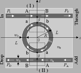 |
Adhering to the most common description for microring-resonators [35,34], the devices are divided into two bent-straight waveguide couplers,
which are connected by segments of the cavity ring. Half-infinite pieces of
straight waveguides constitute the external connections, where the letters A,
B,
![]() ,
,
![]() (external) and a, b,
(external) and a, b,
![]() ,
,
![]() (internal) denote the coupler ports. If
one accepts the approximation that the interaction between the optical waves
in the cavity and in the bus waveguides is negligible outside the coupler
regions, then this functional decomposition reduces the microresonator
description to the mode analysis of straight and bent waveguides, and the
modeling of the bent-straight waveguide couplers.
(internal) denote the coupler ports. If
one accepts the approximation that the interaction between the optical waves
in the cavity and in the bus waveguides is negligible outside the coupler
regions, then this functional decomposition reduces the microresonator
description to the mode analysis of straight and bent waveguides, and the
modeling of the bent-straight waveguide couplers.
Assuming that all transitions inside the coupler regions are sufficiently smooth, such that reflections do not play a significant role for the resonator functioning, we further restrict the model to unidirectional wave propagation, as indicated by the arrows in Figure 4.1. Depending on the specific configuration, this assumption can be justified or not; at least for the structures considered in Section 4.4.2 we observed this approximation to be adequate.
Consider coupler (I) first. Suppose that the straight cores support
![]() guided modes with propagation constants
guided modes with propagation constants
![]() ,
,
![]() . For the cavity,
. For the cavity,
![]() bend modes are taken
into account. Due to the radiation losses, their propagation constants
bend modes are taken
into account. Due to the radiation losses, their propagation constants
![]() ,
,
![]() , are complex valued [114]. Here
, are complex valued [114]. Here
![]() ,
,
![]() and
and
![]() are real
positive numbers. The variables
are real
positive numbers. The variables ![]() ,
, ![]() , and
, and ![]() ,
, ![]() , denote
the directional amplitudes of the properly normalized ``forward'' propagating
(clockwise direction, cf. Figure 4.1) basis modes in the
respective coupler port planes, combined into amplitude (column) vectors
, denote
the directional amplitudes of the properly normalized ``forward'' propagating
(clockwise direction, cf. Figure 4.1) basis modes in the
respective coupler port planes, combined into amplitude (column) vectors
![]() ,
,
![]() , and
, and
![]() ,
,
![]() . A completely analogous reasoning
applies to the second coupler, where a symbol
. A completely analogous reasoning
applies to the second coupler, where a symbol ![]() identifies the mode
amplitudes
identifies the mode
amplitudes
![]() ,
,
![]() , and
, and
![]() ,
,
![]() at the port planes.
at the port planes.
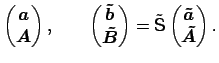
The model of Chapter 3 for unidirectional wave propagation
through the coupler regions provides scattering matrices
S,
![]() , such that the coupler operation is represented as
, such that the coupler operation is represented as
For the guided wave scattering problem, modal powers
![]() and
and
![]() are prescribed at the
In-port A and at the Add-port
are prescribed at the
In-port A and at the Add-port
![]() of the resonator, and one is
interested in the transmitted powers
of the resonator, and one is
interested in the transmitted powers
![]() at port B and
the backward dropped powers
at port B and
the backward dropped powers
![]() at port
at port
![]() . The linear system established by equations (4.1)
and (4.2) is to be solved for
. The linear system established by equations (4.1)
and (4.2) is to be solved for
![]() and
and
![]() , given
values of
, given
values of
![]() and
and
![]() . Due to the linearity of the device
the restriction to an excitation in only one port, here port A, with no
incoming Add-signal
. Due to the linearity of the device
the restriction to an excitation in only one port, here port A, with no
incoming Add-signal
![]() , is sufficient. One obtains
, is sufficient. One obtains
Among the factors in the expressions (4.3) and (4.4) only the inverse
of ![]() can be expected to introduce a pronounced wavelength dependence.
Thus
can be expected to introduce a pronounced wavelength dependence.
Thus
![]() can be viewed as a resonance denominator in matrix form;
resonances appear in case
can be viewed as a resonance denominator in matrix form;
resonances appear in case ![]() becomes nearly singular, i.e. exhibits an
eigenvalue close to zero. This ``resonance condition'' permits a quite
intuitive interpretation: Resonances appear if a field amplitude vector is
excited inside the cavity, that corresponds to a close-to-zero eigenvalue of
becomes nearly singular, i.e. exhibits an
eigenvalue close to zero. This ``resonance condition'' permits a quite
intuitive interpretation: Resonances appear if a field amplitude vector is
excited inside the cavity, that corresponds to a close-to-zero eigenvalue of
![]() , or a unit eigenvalue of
S
, or a unit eigenvalue of
S![]() . That relates to a field which
reproduces itself after propagating consecutively along the right cavity
segment, through coupler (II), along the left cavity segment, and finally
through coupler (I).
. That relates to a field which
reproduces itself after propagating consecutively along the right cavity
segment, through coupler (II), along the left cavity segment, and finally
through coupler (I).
In general, resonances must be expected to involve all bend modes that are
taken into account for the description of the cavity field, due to the
interaction caused by the presence of the straight cores (cf. e.g. the
example of the hybrid cavity ring given in Ref. [69]). If, however,
this direct interaction between the bend modes is weak, the matrices
S![]() and
and
![]() become nearly
diagonal just like
G and
become nearly
diagonal just like
G and
![]() , and resonances can be
ascribed to individual cavity modes. Analogously to the case of standing wave
resonators [115], this viewpoint allows a quantitative characterization
of resonances associated with ``almost isolated'' cavities, where the bus
waveguides are absent. Also for the numerical examples in Section
4.4.2 we found this regime to be realized; resonances can be
classified as belonging to specific bend modes by inspecting the mode
amplitudes that establish inside the cavity at the resonance wavelength.
, and resonances can be
ascribed to individual cavity modes. Analogously to the case of standing wave
resonators [115], this viewpoint allows a quantitative characterization
of resonances associated with ``almost isolated'' cavities, where the bus
waveguides are absent. Also for the numerical examples in Section
4.4.2 we found this regime to be realized; resonances can be
classified as belonging to specific bend modes by inspecting the mode
amplitudes that establish inside the cavity at the resonance wavelength.
In case of a configuration with single mode cavity and bus cores, further
evaluation of expressions (4.3) and (4.4) is presented in
Section 1.4; one obtains the familiar explicit, parameterized
expressions for the transmitted and dropped power, for the free spectral range
and the resonance width, for finesse and Q-factor of the resonances, etc. Here
the above resonance condition means that at coupler (I) the incoming signal
from the bus waveguide is in phase with the wave propagating already along the
cavity, and that it compensates the propagation loss of the cavity round trip.
Resonances appear as a drop in the directly transmitted power
![]() ,
and a simultaneous peak in the dropped power
,
and a simultaneous peak in the dropped power
![]() . Assuming that
this reasoning is also applicable to a multimode configuration with weak
interaction, one can establish separate resonance conditions for the
individual cavity modes, which in general will be satisfied at different
wavelengths. The power spectrum of the microresonator shows a systematically
repeating pattern with multiple extrema, where each resonance corresponds to
cavity modes of different orders. See Figure 4.9 for an
example.
. Assuming that
this reasoning is also applicable to a multimode configuration with weak
interaction, one can establish separate resonance conditions for the
individual cavity modes, which in general will be satisfied at different
wavelengths. The power spectrum of the microresonator shows a systematically
repeating pattern with multiple extrema, where each resonance corresponds to
cavity modes of different orders. See Figure 4.9 for an
example.
 S
S