|
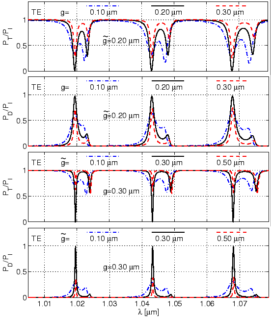
For the simulations shown in Figure 4.15, changing the separation distance also affects the position of the resonances. In both cases, enlarging one of the separation distances, increases the resonance wavelength.
The simulation results of Figure 4.15 show a very
peculiar behaviour for
![]() , for which the resonant through power and
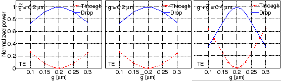
drop power attain extrema. Figure 4.16 shows the variation of the
resonant power transmission for different settings of the separation distances
for the ring resonator. As evident from these plots, when both coupler gaps
are identical, the drop power is maximum (
, for which the resonant through power and
drop power attain extrema. Figure 4.16 shows the variation of the
resonant power transmission for different settings of the separation distances
for the ring resonator. As evident from these plots, when both coupler gaps
are identical, the drop power is maximum (![]() ), and the through
power is minimum (
), and the through
power is minimum (![]() ). This can be explained as following.
). This can be explained as following.
 |
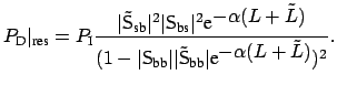
In Section 1.4.3, we derived an expression for the drop
power at resonance for a microresonator configuration with identical couplers
(
![]() ). Generalizing that expression to non-identical couplers (
). Generalizing that expression to non-identical couplers (
![]() ) gives
) gives
If the cavity mode under consideration has negligible attenuation (
![]() ), and if the coupling is assumed to be lossless (power is conserved,
i.e.
), and if the coupling is assumed to be lossless (power is conserved,
i.e.
![]() S
S![]() ,
,
![]() ), then
), then
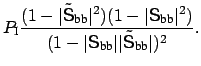
For
![]() S
S![]() , this leads to
, this leads to
![]() , i.e. complete transfer of the input power to
the Drop-port. This implies
, i.e. complete transfer of the input power to
the Drop-port. This implies
![]() S
S![]() ,
,
![]() S
S![]() ,
,
![]() S
S![]() ,
which is realized for identical couplers (
,
which is realized for identical couplers (
![]() ), as illustrated in
Figure 4.16.
), as illustrated in
Figure 4.16.
If the attenuation losses are not negligible, then the ideal complete power
transfer is not achieved. This becomes apparent for the simulation
results of the disk resonator, shown in Figure 4.17. For
the low loss TE![]() modes, the power drop is almost 1. But as the TE
modes, the power drop is almost 1. But as the TE![]() mode
has substantially higher attenuation (see Figure 3.8), the TE
mode
has substantially higher attenuation (see Figure 3.8), the TE![]() resonance power drop for the symmetrical resonator is far from complete power transfer (also see Fig. 4.7).
resonance power drop for the symmetrical resonator is far from complete power transfer (also see Fig. 4.7).
 |
Comparison of the first two plots of Figure 4.16 shows that for
low loss case, ![]() and
and ![]() have almost identical effects on
have almost identical effects on
![]() ,
,
![]() at resonance. Moreover, the plots in
Figure 4.15 and 4.17 reveal that
as one of the gaps increases, the width of the resonance reduces.
at resonance. Moreover, the plots in
Figure 4.15 and 4.17 reveal that
as one of the gaps increases, the width of the resonance reduces.